CommoFreq
Member
ALCON,
If you haven't taken the time to review some of the information that I posted about how antennas function, now would be a good time to. In this post, I will be walking you through a build that I finished a few days ago, and as I do so, we will be taking our antenna knowledge to the next level.
Let's talk for a moment about antenna tuners. These are a must if you want to use a wide range of different frequencies, but with one antenna. Without getting into the boring stuff, what this does is it keeps radio waves from being reflected back into your radio and burning it up, when using an antenna that has a length which has nothing to do with the frequency that you want to use. Yes, there are still waves being reflected back, because the antenna is the wrong length. But this device catches them before they get to your radio, and bounces them back out again.
I decided to build an antenna, cut at a length that supports 1.8MHz, which is extremely low frequency. In fact, for all practical purposes, it is the lowest frequency that is usable to us normal people. And there's a really important reason why I did this - you see, antenna tuners can tune antennas that are longer than the frequency you want to use, but not shorter.
In other words, if I had an antenna that was cut for say, 440MHz (a relatively high UHF frequency), and I was transmitting on, say, a CB channel 19, well, an antenna tuner wouldn't work. The length of the antenna has to be at least the channel 19 frequency length, or longer. Get it? So, I went with the longest possible, that being, 1.8MHz.
Now, let's talk for a moment about transmission line. This is whatever you use to connect your antenna to your radio. For most of you, this involves using 50-ohm coax cable, with a PL259 connector on the end. For vehicular installations, this is really the only possibility. However, if you are setting up a base station, I recommend using the other possibility - 450-ohm "ladder line". The reason being, it gets your signal to the antenna much more efficiently, and thus, less of it gets lost as heat on its way to the antenna. That's right - just because your radio sends a signal to the antenna, doesn't mean that 100% of your signal will make it there.
And of course, there's some boring stuff about ladder line vs. coax cable, and balanced and unbalanced line, but I will spare you that until another time. So, let's start building.
Here is what the completed antenna will look like:
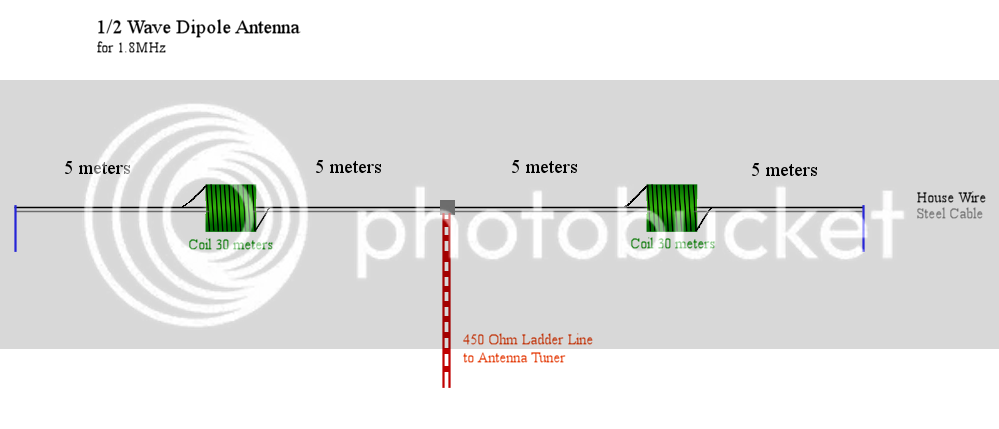
Very few people have enough space to hang 80 meters of wire. What we've done here, is we are coiling that wire onto giant tubes, so that the antenna is electrically 80 meters long, but physically around 20 meters long. That means about 75% of the antenna will be on the coils. It's not so wonderful to do this, but hey, we also don't live in a perfect world either.
I happened across 50 meters of house wiring. If you've seen that stuff before, you'll know that it is composed of 3 wires, all made of solid copper. The first step is to strip that stuff down and separate the wires inside. And man, let me tell you - it is a bitch to do. But just keep in mind, all of the hard work is worth it.
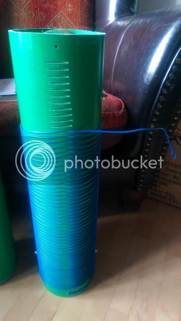
Now it's time to build the coils!
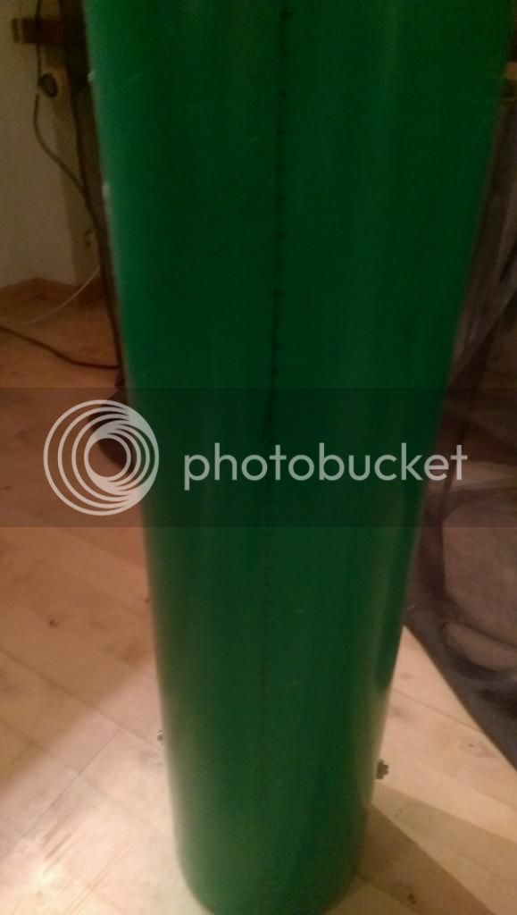
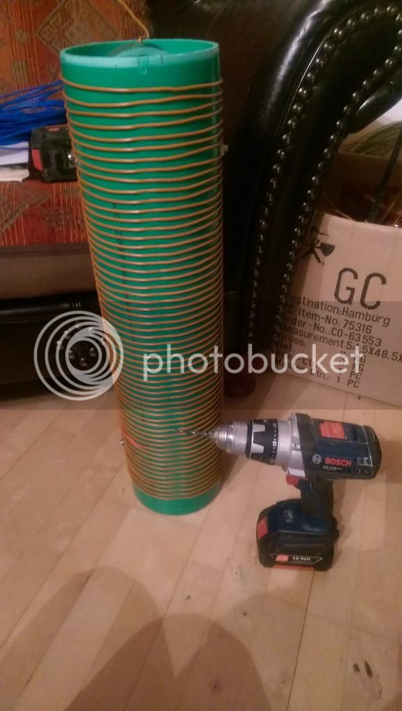
So, I also happened across some large air-duct tubing, roughly 16cm in diameter. After doing some math, I cut it into two pieces, 65cm long. You probably can't see it very well, but down the length of the pipes, I marked off 1cm marks, well, 58 of them to be exact. We are going to wrap this wire around the pipe, 58 times, with a 1cm distance in between the turns. No, there's no reason for that as far as the radio waves go - I just arbitrarily decided that's how it had to be. Anyhow, we are making these marks, because we are going to use a cutter to cut notches (not too deep) into the pipe, so that the wire fits into them and doesn't slide.
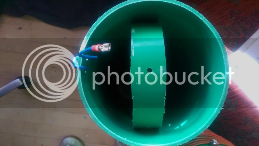
Cut off two small sections, and cram them into the ends of the main piece, and bolt them into place.
Kinda like this:
Damn. I ran out of wire. Yeah, when I was skinning the house wiring cable, and trying to separate the wires inside, I cheated, and cut the cable in half to make it easier. So now I have to splice it back together again.
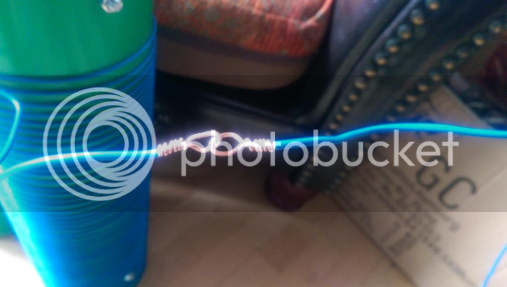
I'm not gonna lie - soldering sucks. When you make a splice, this is how you do it. This is called a "Western Union" or a "telegraph" splice.
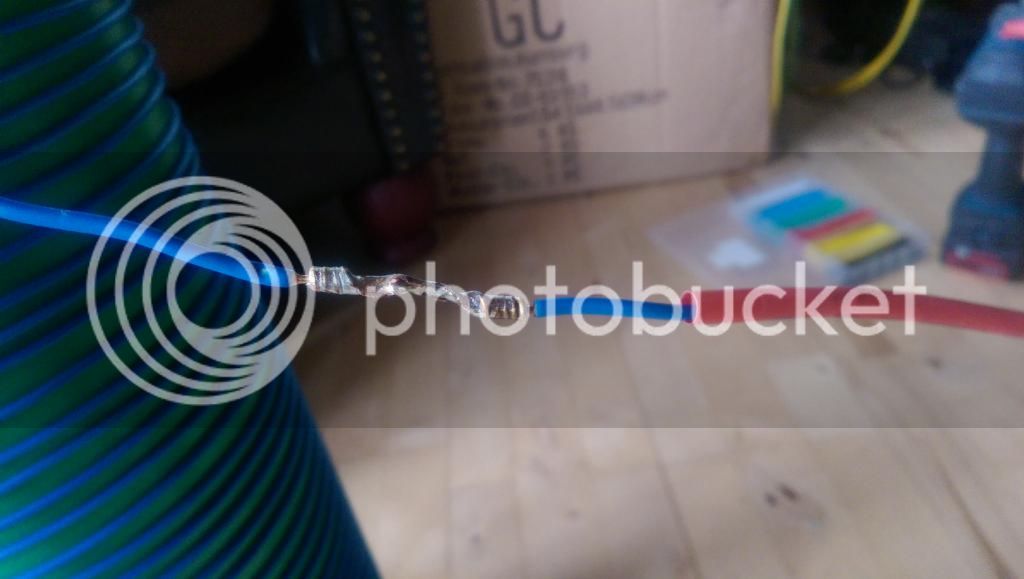
Now you fill it with solder, and note the red shrink tube.
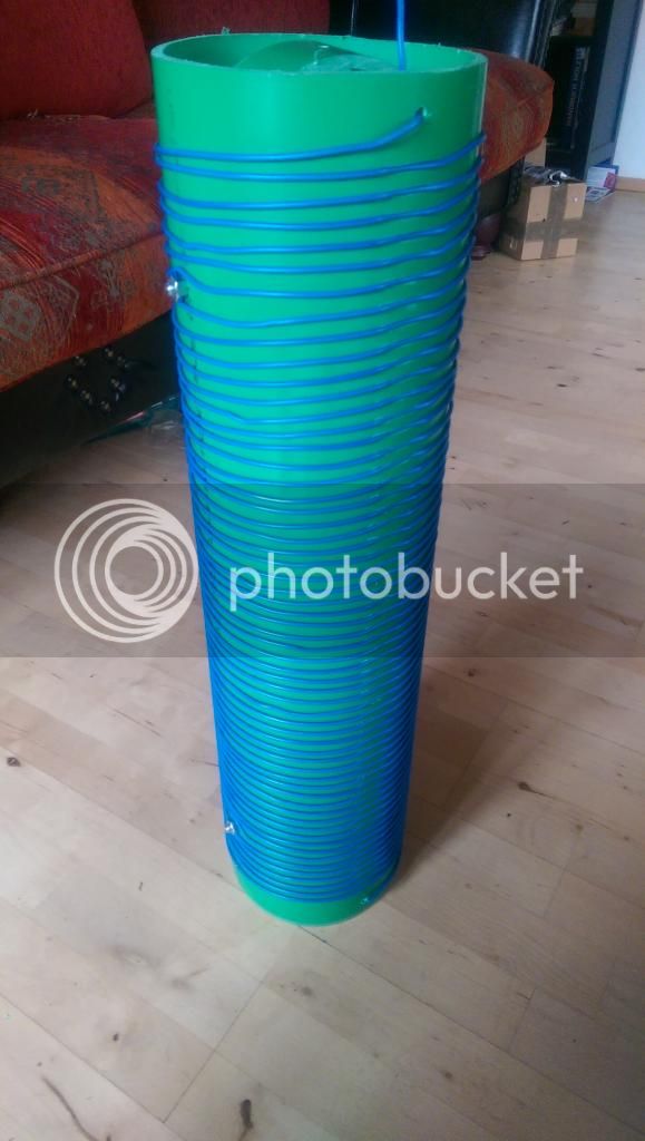
And this is what a completed coil looks like.
Now you make the other one.
Please bear in mind, the wire on the coils MUST be the exact same length. If you put 30 meters and 65 centimeters on one coil, then you must do the same for the other.
Now it's time to build the center piece.
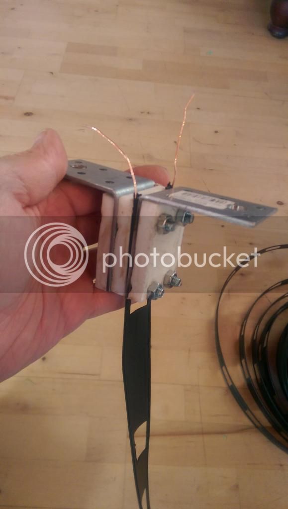
So, what you are looking at is two brackets, bolted together. The white material is actually a cutting board that I stole from the kitchen. You want the holes to be small through the cutting board, and large through the brackets, so that the bolts don't touch the brackets once you have them in. This keeps the brackets from being electrically connected. I had a hard time doing this, so I just sandwiched the ladder line into the mixture.
Now, you will first connect steel cable to the brackets, and secure the ends of them to something. Anything. It could be two trees, for example. I used a couple of poles that I attached to the ends of my roof (sorry, not pictured). The point of the steel cable is to hold the weight of the coils. Yes, they are heavy.
Then, you attach the 5meter wire segments to the coils and to the ladder line as shown in the diagram. You might want to consider using connectors as you put this thing together.
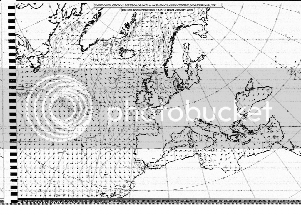
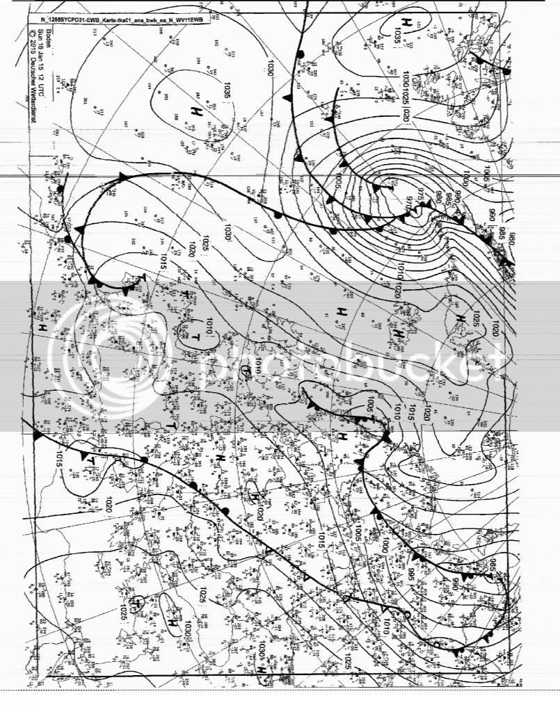
Just to give you an idea of how well it works, here's a couple of WeatherFaxes that I received from my location around Salzburg, Austria:
This one was transmitted from England:
And this one came from Hamburg:
I'll show you guys how to do that in another tutorial at another time. If you have any questions, please feel free to ask away.
If you haven't taken the time to review some of the information that I posted about how antennas function, now would be a good time to. In this post, I will be walking you through a build that I finished a few days ago, and as I do so, we will be taking our antenna knowledge to the next level.
Let's talk for a moment about antenna tuners. These are a must if you want to use a wide range of different frequencies, but with one antenna. Without getting into the boring stuff, what this does is it keeps radio waves from being reflected back into your radio and burning it up, when using an antenna that has a length which has nothing to do with the frequency that you want to use. Yes, there are still waves being reflected back, because the antenna is the wrong length. But this device catches them before they get to your radio, and bounces them back out again.
I decided to build an antenna, cut at a length that supports 1.8MHz, which is extremely low frequency. In fact, for all practical purposes, it is the lowest frequency that is usable to us normal people. And there's a really important reason why I did this - you see, antenna tuners can tune antennas that are longer than the frequency you want to use, but not shorter.
In other words, if I had an antenna that was cut for say, 440MHz (a relatively high UHF frequency), and I was transmitting on, say, a CB channel 19, well, an antenna tuner wouldn't work. The length of the antenna has to be at least the channel 19 frequency length, or longer. Get it? So, I went with the longest possible, that being, 1.8MHz.
Now, let's talk for a moment about transmission line. This is whatever you use to connect your antenna to your radio. For most of you, this involves using 50-ohm coax cable, with a PL259 connector on the end. For vehicular installations, this is really the only possibility. However, if you are setting up a base station, I recommend using the other possibility - 450-ohm "ladder line". The reason being, it gets your signal to the antenna much more efficiently, and thus, less of it gets lost as heat on its way to the antenna. That's right - just because your radio sends a signal to the antenna, doesn't mean that 100% of your signal will make it there.
And of course, there's some boring stuff about ladder line vs. coax cable, and balanced and unbalanced line, but I will spare you that until another time. So, let's start building.
Here is what the completed antenna will look like:
Very few people have enough space to hang 80 meters of wire. What we've done here, is we are coiling that wire onto giant tubes, so that the antenna is electrically 80 meters long, but physically around 20 meters long. That means about 75% of the antenna will be on the coils. It's not so wonderful to do this, but hey, we also don't live in a perfect world either.
I happened across 50 meters of house wiring. If you've seen that stuff before, you'll know that it is composed of 3 wires, all made of solid copper. The first step is to strip that stuff down and separate the wires inside. And man, let me tell you - it is a bitch to do. But just keep in mind, all of the hard work is worth it.
Now it's time to build the coils!
So, I also happened across some large air-duct tubing, roughly 16cm in diameter. After doing some math, I cut it into two pieces, 65cm long. You probably can't see it very well, but down the length of the pipes, I marked off 1cm marks, well, 58 of them to be exact. We are going to wrap this wire around the pipe, 58 times, with a 1cm distance in between the turns. No, there's no reason for that as far as the radio waves go - I just arbitrarily decided that's how it had to be. Anyhow, we are making these marks, because we are going to use a cutter to cut notches (not too deep) into the pipe, so that the wire fits into them and doesn't slide.
Cut off two small sections, and cram them into the ends of the main piece, and bolt them into place.
Kinda like this:
Damn. I ran out of wire. Yeah, when I was skinning the house wiring cable, and trying to separate the wires inside, I cheated, and cut the cable in half to make it easier. So now I have to splice it back together again.
I'm not gonna lie - soldering sucks. When you make a splice, this is how you do it. This is called a "Western Union" or a "telegraph" splice.
Now you fill it with solder, and note the red shrink tube.
And this is what a completed coil looks like.
Now you make the other one.
Please bear in mind, the wire on the coils MUST be the exact same length. If you put 30 meters and 65 centimeters on one coil, then you must do the same for the other.
Now it's time to build the center piece.
So, what you are looking at is two brackets, bolted together. The white material is actually a cutting board that I stole from the kitchen. You want the holes to be small through the cutting board, and large through the brackets, so that the bolts don't touch the brackets once you have them in. This keeps the brackets from being electrically connected. I had a hard time doing this, so I just sandwiched the ladder line into the mixture.
Now, you will first connect steel cable to the brackets, and secure the ends of them to something. Anything. It could be two trees, for example. I used a couple of poles that I attached to the ends of my roof (sorry, not pictured). The point of the steel cable is to hold the weight of the coils. Yes, they are heavy.
Then, you attach the 5meter wire segments to the coils and to the ladder line as shown in the diagram. You might want to consider using connectors as you put this thing together.
Just to give you an idea of how well it works, here's a couple of WeatherFaxes that I received from my location around Salzburg, Austria:
This one was transmitted from England:
And this one came from Hamburg:
I'll show you guys how to do that in another tutorial at another time. If you have any questions, please feel free to ask away.